


Contact: Ms. Clara
E-mail:Clara@tianyidz.com
info@tianyidz.com
Skype:tianyidz1998
Factory Address ��NO.K43,Jiahai Industrial Zone,Huangpi District,Wuhan,Hubei province,China.430312
Cell/Whats app:
+86 180 4052 0982
Office Tel:+86 27 6189 5560
Fax:+86 27 6189 5570
PRODUCTS
Position��INDEX-PRODUCTS-ETEEP software
Compliant with IEC and GB Standards
The design and calculation of substation grounding grids is not a new technology, yet it remains a common issue during project completion and acceptance. Often, the measured results of the grounding grid and its associated technical parameters do not match the design values or fail to meet national technical standards. Consequently, additional corrective measures must be taken at a higher cost. The main causes include inaccurate or incorrect measurement of soil parameters and overly simplistic or unscientific design, layout, and calculation methods.
Currently, there are two main methods for calculating grounding grid parameters: formula-based calculations and numerical simulations. While the former is simpler, it is only suitable for uniform soil parameters and regular grid layouts. The latter is more flexible, supporting arbitrary soil distributions and grid layouts with higher accuracy.
ETEEP (Electrical Engineering Grounding and Electromagnetic Environment Program) integrates both formula-based and numerical simulation methods. It meets a range of user needs and is more cost-effective—about one-quarter the price—compared to similar foreign software (e.g., C***S), while offering more powerful functions.
ETEEP provides three methods to create soil (substation site) calculation models, depending on the nature and source of the data:
- For apparent resistivity data measured at various locations and depths, users can input or import data into the interface (Figure 1a) and use the "Layer" function to auto-generate layers (Figure 1d).
- For interpreted true resistivity data (layered), input or import the data into the interface (Figure 1b) and apply the layering function (Figure 1d).
- For existing models, data can be directly entered into the interface (Figure 1c). Users can click the “Verify” button to compare the surface apparent resistivity response curve to measured curves, view error values, and obtain recommended new models.
ETEEP enables users to calculate the short-circuit current that flows into the ground through the grounding grid during a single-phase fault. Users only need to input relevant parameters (Figure 2a), and the software calculates the required current using equivalent impedance, substation voltage and capacity, and grounding impedance (Figure 2b).
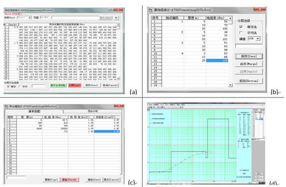
Fig,1 Creating Soil Calculation Models
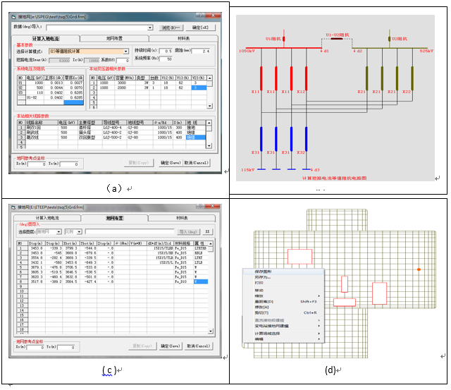
Fig,2 Creating Short-Circuit Current & Grid Layout Models
Three methods are available for modeling grounding grid layouts:
- DWG Import: Use AutoCAD to create a dedicated layer (e.g., horizontal grid) on a 1:1000 or 1:2000 DWG equipment layout. Define the layout area with a rectangle tool, then import and configure it in the ETEEP interface (Figure 2c) to complete modeling.
- Parameter Input: Input key node coordinates directly into the interface (Figure 2c), set properties (e.g., material type, grid spacing, chamfering), and generate the layout (Figure 2d).
- Drag-and-Drop Modeling: Offers intuitive editing, deletion, modification, object movement, chamfering, addition of vertical ground rods, and dimension editing using mouse actions. These actions are synchronized with the parameter table and allow for zooming, distance measuring, coordinate reading, and file operations.
Once modeling is complete, click “Run (R)” > “Grounding and Electromagnetic Environment” to start the simulation. The software produces comprehensive outputs including:
- Calculation reports (Word/XLS format)
- Various graphs and 3D images of electric field potentials and touch voltages (JPG format)

Fig,3 Creating Short-Circuit Current & Grid Layout Models
ETEEP can also generate construction drawings automatically based on the layout model. Users can select options via the drawing dialog (Figure 4) to produce detailed construction diagrams.
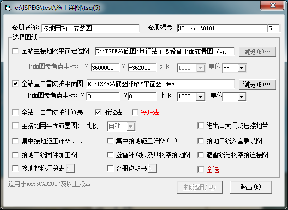
Fig. 4 Interface for the generating construction drawings
For more details about ETEEP software, please contact our company.

Factory Address ��NO.K43,Jiahai Industrial Zone,Panlongcheng,Huangpi District, Wuhan,Hubei Province,China.430312
Office Tel: +86 27 6189 5560 Fax: +86 27 6189 5570
Contact: Ms. Clara Ms. Lisa
Cell/whats app: +86 180 4052 0982 +86 150 7122 7283
Skype��tianyidz1998 E-mail:Clara@tianyidz.com info@tianyidz.com lisa@tianyidz.com
Has passed the IS09001:2008 quality management system and YY / T0287 - 2003 (1S013485:2003) medical device quality management system certification
Wuhan Tian Yi Electronics Co., Ltd. all rights reserved.